Monday, December 12, 2011
Sunday, March 20, 2011
Fiber-Optic Cable

installation dificulty. Despite these disadvantages, fiber-optic cable is now often installed into buildings by telephone companies as the cable of choice. The center conductor of a ?ber-optic cable is a ?ber that consists of
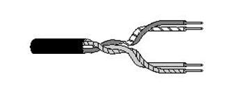
highly refined glass or plastic designed to transmit light signals with little loss. A glass core supports a longer cabling distance, but a plastic core is typically easier to work with. The ?ber is coated with a cladding or a gel that re?ects signals back into the fiber to reduce signal loss. A plastic sheath protects the fiber (see Figure. A fiber-optic network cable consists of two strands separately enclosed in plastic sheaths. One strand sends and the other receives.
Two types of cable con?gurations are available: loose and tight
(some are as small as 8.3 microns) must be lined up with extreme precision to prevent excessive signal loss.

Category 5 UTP CABLES
Category 5. This data-grade cable, which also consists of four twisted-pairs, is suitable for data rates up to 100Mbps. Most new cabling systems for 100Mbps data rates are designed around Category 5 cable.
Category 4 UTP CABLES
Category 4. This data-grade cable, which consists of four twisted-pairs, is suitable for data rates up to 16Mbps.
Category 3 UTP CABLES
Category 3. As the lowest data-grade cable, this type of cable generally is suited for data rates up to 10Mbps. Some innovative schemes utilizing new standards and technologies, however, enable the cable to support data rates up to 100Mbps. Category 3, which uses four twisted pairs with three twists per foot, is now the standard cable used for most telephone installations.
Categories 1 and 2. UTP CABLES
Categories 1 and 2. These voice-grade cables are suitable only for voice and for low data rates (below 4Mbps). Category 1 was once the standard voice-grade cable for telephone systems. The growing need for data-ready cabling systems, however, has caused Categories 1 and 2 cable to be supplanted by Category 3 for new installations.
Unshielded Twisted-Pair (UTP) Cable
Unshielded twisted-pair cable doesn't incorporate a braided shield into its structure. However, the characteristics of UTP are similar in many ways to STP, differing primarily in attenuation and EMI. As shown in Figure , several twisted pairs can be bundled together in a single cable. These pairs are typically color-coded to distinguish them.

Telephone systems commonly use UTP cabling. Network engineers can sometimes use existing UTP telephone cabling (if it is new enough and of a high enough quality to support network communications) for network cabling. UTP cable is a latecomer to high-performance LANs because engineers only recently solved the problems of managing radiated noise and susceptibility to EMI. Now, however, a clear trend toward UTP is in operation, and all new copper-based cabling schemes are based on UTP.
Connectors for STP
AppleTalk and Token Ring networks can be cabled using UTP cable and RJ-45 connectors (described later in this chapter), but both net- works originated as STP cabling systems. For STP cable, AppleTalk also employs a DIN-type connector. Figure 3.15 shows an IBM connector connected to a network card having a DIN (DB-9) connectorusing a STP cable. The IBM Data Connector is unusual because it doesn't come in two gender configurations. Instead, any IBM Data Connector can be snapped to any other IBM Data Connector.
Shielded Twisted-Pair (STP) Cable

shield. Various types of STP cable exist, some that shield each pair individually and others that shield several pairs. The engineers who design a network's cabling system choose the exact configuration. IBM designates several twisted-pair cable types to use with their Token Ring network design, and each cable type is appropriate for a given kind of installation. A completely different type of STP is the standard cable for Apple's AppleTalk network.Because so many different types of STP cable exist, describing pre- cise characteristics is dificult. The following sections, however, offer
some general guidelines.
Twisted-Pair Cable
Twisted-pair cable has become the dominant cable type for all new network designs that employ copper cable. Among the several reasons for the popularity of twisted-pair cable, the most significant is its low cost. Twisted-pair cable is inexpensive to install and offers the lowest cost per foot of any cable type. Your telephone cable is an
example of a twisted-pair type cable. A basic twisted-pair cable consists of two strands of copper wire
twisted together (see Figure). The twisting reduces the sensitivi- ty of the cable to EMI and also reduces the tendency of the cable to radiate radio frequency noise that interferes with nearby cables and electronic components, because the radiated signals from the twisted wires tend to cancel each other out. (Antennas, which are purposely designed to radiate radio frequency signals, consist of parallel, not twisted, wires).

Twisting of the wires also controls the tendency of the wires in thepair to cause EMI in each other. As noted previously, whenever twowires are in close proximity, the signals in each wire tend to producecrosstalk in the other. Twisting the wires in the pair reduces crosstalkin much the same way that twisting reduces the tendency of thewires to radiate EMI.A twisted-pair cable is used in most cases to connect a PC to either a HUB or a MAU. "Connectivity Devices and Transfer Mechanisms." Two types oftwisted-pair cable are used in LANs: shielded and unshielded,
Coaxial Cable
Coaxial cables were the ?rst cable types used in LANs. As shown in Figure coaxial cable gets its name because two conductors share a common axis; the cable is most frequently referred to as a "coax." A type of coaxial cable that you may be familiar with is your television cable.

The components of a coaxial cable are as follows:
A center conductor, although usually solid copper wire, is sometimes made of stranded wire. An outer conductor forms a tube surrounding the center conductor. This conductor can consist of braided wires, metallicfoil, or both. The outer conductor, frequently called the shield,serves as a ground and also protects the inner conductor fromEMI.
An insulation layer keeps the outer conductor spaced evenlY from the inner conductor. A plastic encasement (jacket) protects the cable from damage.
CABLE MEDIA
three types of network cabling media, as follows:
Coaxial cable
Twisted-pair cable
Fiber-optic cable
Electromagnetic Interference
Electromagnetic interference (EMI) consists of outside electromagnetic noise that distorts the signal in a medium. When you listen to an AM radio, for example, you often hear EMI in the form of noise caused by nearby motors or lightning. Some network media are more susceptible to EMI than others. Crosstalk is a special kind of interference caused by adjacent wires. Crosstalk occurs when the signal from one wire is picked up by another wire. You may have experienced this when talking on a telephone and hearing another conversation going on in the background. Crosstalk is a particularly signi?cant problem with computer networks because large numbers of cables often are locatedclose together, with minimal attention to exact placement.
Attenuation
Attenuation is a measure of how much a signal weakens as it travels through a medium, Attenuation is a contributing factor to why cable designs must specify limits in the lengths of cable runs. When signal strength falls below certain limits, the electronic equipment that receives the signal can experience difIculty isolating the original signal from the noise present in all electronic transmissions. The effect is exactly like trying to tune in distant radio signals. Even if you can lock on to the signal on your radio, the sound generally still contains more noise than the sound for a local radio station. As mentioned in the previous chapters, repeaters are used to regenerate signals; hence one solution to deal with attenuation is to add a repeater.
Time-Division Multiplexing
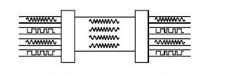
Time-division multiplexing (TDM) divides a channel into time slots that are allocated to the data streams to be transmitted, as illustrated in Figure If the sender and receiver agree on the time-slot assignments, the receiver can easily recover and reconstruct the original data streams.

Notice that Channel B is allocated more time slots than Channel A, and that Channel C is allocated the fewest time slots. Channel D is idle, so no slots are allocated to it. To make this procedure work, the data transmitted for each time slot includes a control field thatidenti?es the channel to which the data in the time slot should be assigned.

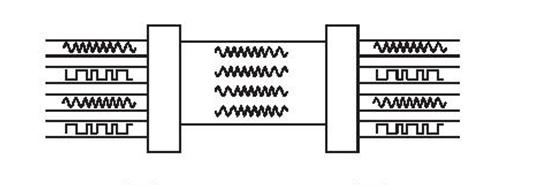
TDM transmits the multiplexed signal in baseband mode. Interest- ingly, this process makes it possible to multiplex a TDM signal as one of the data channels on an FDM system. Conventional TDM equipment utilizes Fixed time divisions and allocates time to a channel, regardless of that channel's level of activity.If a channel isn't busy, its time slot isn't being fully utilized. Because The time divisions are programmed into the conFigurations of the multiplexers, this technique is often referred to as synchronous TDM. If using the capacity of the data medium more efIciently is important, a more sophisticated technique, statistical time-division multiplexing (StatTDM), can be used. A stat-mux uses the time-slot
technique but allocates time slots based on the trafic demand on theindividual channels, as illustrated in FigureNotice that Channel B is allocated more time slots than Channel A, and that Channel C is allocated the fewest time slots. Channel D is idle, so no slots are allocated to it. To make this procedure work, the data transmitted for each time slot includes a control field thatidenti?es the channel to which the data in the time slot should be assigned.
Frequency-Division Multiplexing
Figure illustrates frequency-division multiplexing (FDM). This technique works by converting all data channels to analog form. Each analog signal can be modulated by a separate frequency (called a "carrier frequency") that makes it possible to recover that signal during the demultiplexing process. At the receiving end, the demultiplexer can select the desired carrier signal and use it to extract the data signal for that channel. FDM can be used in broadband LANs. (A standard for Ethernet also exists.) One advantage of FDM is that it supports bidirectional signaling on the same cable. That is, a frequency can originate from both ends of the transmission media at once.
TRANSMISSION MEDIA
Each type of transmission media has special characteristics that make it suitable for a specific type of service. You should be familiar with these characteristics for each type of media:
Cost
Installation requirements
Bandwidth
Band usage (baseband or broadband)
Attenuation
Immunity from electromagnetic interference
These characteristics are all important. When you design a network for a company, all these factors play a role in the decision concerning what type of transmission media should be used.
Cost
Installation Requirements
Installation requirements typically involve two factors. One is that some transmission media require skilled labor to install. Bringing in a skilled outside technician to make changes to or replace resources on the network can bring about undue delays and costs. The second has to do with the actual physical layout of the network. Some types of transmission media install more easily over areas where people are spread out, whereas other transmission media are easier to bring to
clusters of people or a roaming user.
Bandwidth
In computer networking, the term bandwidth refers to the measure of the capacity of a medium to transmit data. A medium that has a high capacity, for example, has a high bandwidth, whereas a medium that has limited capacity has a low bandwidth Bandwidth can be best explained by using water hoses as an analogy. If a half-inch garden hose can carry water FLow from a trickle up to two gallons per minute, then that hose can be said to have a band width of two gallons per minute. A four-inch ?re hose, however, might have a bandwidth that exceeds 100 gallons per minute. Data transmission rates are frequently stated in terms of the bits that can be transmitted per second. An Ethernet LAN theoretically can
Band Usage (Baseband or Broadband)
The two ways to allocate the capacity of transmission media are with baseband and broadband transmissions. Baseband devotes the entire capacity of the medium to one communication channel. Broadband enables two or more communication channels to share the band width of the communications medium. Baseband is the most common mode of operation. Most LANs function in baseband mode, for example. Baseband signaling can be accomplished with both analog and digital signals. Although you might not realize it, you have a great deal of experience with broadband transmissions. Consider, for example, that the TV cable coming into your house from an antenna or a cable provider is a broadband medium. Many television signals can share the bandwidth of the cable because each signal is modulated using a separately assigned frequency. You can use the television tuner to select the frequency of the channel you want to watch. This technique of dividing bandwidth into frequency bands is called frequency-division multiplexing (FDM) and works only with analog signals. Another technique, called time-division multiplexing (TDM), supports digital signals. Both of these types of multiplexing contrasts the difference between baseband and broadband modes of operation.
Multiplexing
Multiplexing is a technique that enables broadband media to support multiple data channels. Multiplexing makes sense under a number of circumstances: When media bandwidth is costly. A high-speed leased line, such as a T1 or T3, is expensive to lease. If the leased line has sufIcient bandwidth, multiplexing can enable the same line to carry mainframe, LAN, voice, video conferencing, and various other data types. When bandwidth is idle. Many organizations have installed
FIber-optic cable that is used to only partial capacity. With the proper equipment, a single ?ber can support hundreds of
megabits-or even a gigabit or more-of data per second. When large amounts of data must be transmitted through low-
capacity channels. Multiplexing techniques can divide the original data stream into several lower-bandwidth channels, each of which can be transmitted through a lower-capacity medium. The signals then can be recombined at the receiving end.

Multiplexing refers to combining multiple data channels for transmission on a common medium. Demultiplexing refers to recovering the original separate channels from a multiplexed signal. Multiplexing and demultiplexing are performed by a multiplexer (also called a mux), which usually has both capabilities.
transmit 10 million bits per second and has a bandwidth of 10 megabits per second (Mbps). The bandwidth that a cable can accommodate is determined in part by the cable's length. A short cable generally can accommodate
greater bandwidth than a long cable, which is one reason all cable designs specify maximum lengths for cable runs. Beyond those limits, the highest-frequency signals can deteriorate, and errors begin to occur in data signals. You can see this by taking a garden hose and snapping it up and down. You can see the waves traveling down the hose get smaller as they get farther from your hand. This loss of the wave's amplitude represents attenuation, or signal degradation.
One main factor in the purchase decision of any networking component is the cost. Often the fastest and most robust transmission media is desired, but a network designer must often settle for some thing that is slower and less robust, because it more than suf?ces for the business solution at hand. The major deciding factor is almost always price. It is a rare occasion in the ?eld that the sky is the limit for installing a network. As with nearly everything else in the computer field, the fastest technology is the newest, and the newest is the most expensive. Over time, economies of scale bring the price down, but by then, a newer technology comes along.
Subscribe to:
Comments (Atom)